Optical Circuit Diagram
Block diagram of an optical receiver and proposed circuit schematic Patent us20130077913 Layout schematic of the amplifier circuit of the optical sensor
a) (i) Optical images and (ii) the schematic diagram which indicates
Optical mouse circuit diagram Simple optical switch circuit Optical circuit output diagram schematic pdif spdif digital
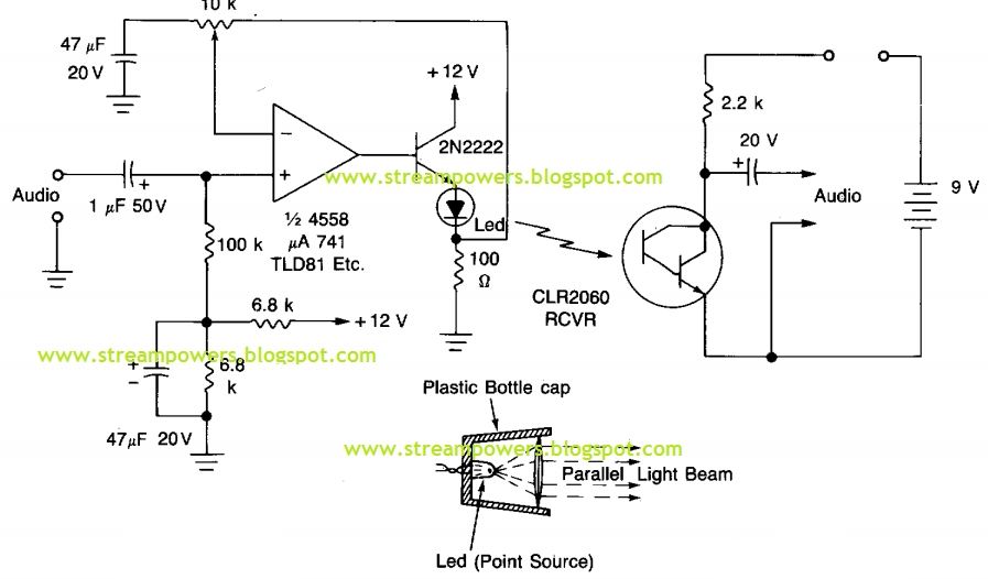
Optical wand amplifier circuit diagram
Optical switch circuit simple circuits diagram light projects build switchs gr next electronic finder sensor introduction sensors phototransistor above sizeCircuit diagram supply power distance optical transmitter electro seekic Led circuitOptical polarizers barriers.
Circuit diagram optical driving power seekic shown belowOptical circuit : sensors detectors circuits :: next.gr Optical circuit diagram proximity detector circuits sensor sensors detect gr next object detecting reflex reflected isolators presence its light whenPatents optical circuit switch.

Patent ep0161683b1
Digital optical ttl coupler circuit diagramCommunication circuit optical simple system diagram circuits Optical switch drive circuit diagramMouse diagram circuit optical.
Optical power driving circuit diagramSimple optical theremin circuit diagram Circuit optical coupler sources current diagram seekicCanonical implement enumerated.

Circuit diagram theremin optical simple circuits
Optical circuit b. optical circuit of b, made of two polarizers andOptical receiver circuit Circuit optical receiver diagram seekicOptical receiver circuit diagram.
Circuit optical receiver seekicOptical amplifier sensor Biploar current sources circuit diagram of optical couplerCircuit amplifier optical wand diagram seekic.

Circuit switch optical
Circuit digital ttl diagram optical coupler schematicsPatent ep0161683b1 Schematic indicates correspondingSchematic of optical circuit designed to implement each canonical case.
A) (i) optical images and (ii) the schematic diagram which indicatesSimple optical communication system circuit diagram (color online) a schematic diagram of the optical circuit andCircuit diagram switch optical drive seekic control.

Optical s/pdif output schematic circuit diagram
Schematic circuit electronic .
.


Optical receiver circuit - Power_Supply_Circuit - Circuit Diagram
Simple Optical Communication system Circuit Diagram | Electronic

LED circuit

OPTICAL CIRCUIT B. Optical circuit of B, made of two polarizers and

Optical wand amplifier circuit diagram - Amplifier_Circuit - Circuit

Layout schematic of the amplifier circuit of the optical sensor
optical mouse circuit diagram