Power Valve Circuit Diagram
Solenoid valve – tlfong01.blog Diagram engine diesel valve system energies stroke internal g001 cooling combination ci timing wiring combustion text 1024 oiling navigation post Valve way schematic motorized lab control circuitlab created using
UK Vintage Radio Repair and Restoration - How Do Valves Work?
Wiring honeywell actuator Pedal tech: diy valve overdrive pedal Pressure reducing valve working principle and its internal construction
Valve circuits
Electric valve ball wiring diagram_tianjin tianfei high-tech valve co.,ltdValve electric inner ball thread way The circuit diagram of the new power electronics solution for twoControl circuit of the electric valve.
Valves circuitWay valve diagram valves impulse logic its tv naming pneumatic Solenoid valve wiring2/3-way modulating/on-off motorized ball valve.

Electric valve actuator wiring diagram
Valve circuits 3Solenoid circuitlab Power valve circuit voltage tube stabiliser series valves small amplifier typical fig controlMotor operated valve wiring diagram.
Actuator wiring actuators rotork connectInner thread 3 way electric ball valve Solenoid valve wiring valves circuit relay schematic arduino transistor control power sensor supply electron 12v 5v water high bat blinkPressure reducing circuit principle construction understand.

Uk vintage radio repair and restoration
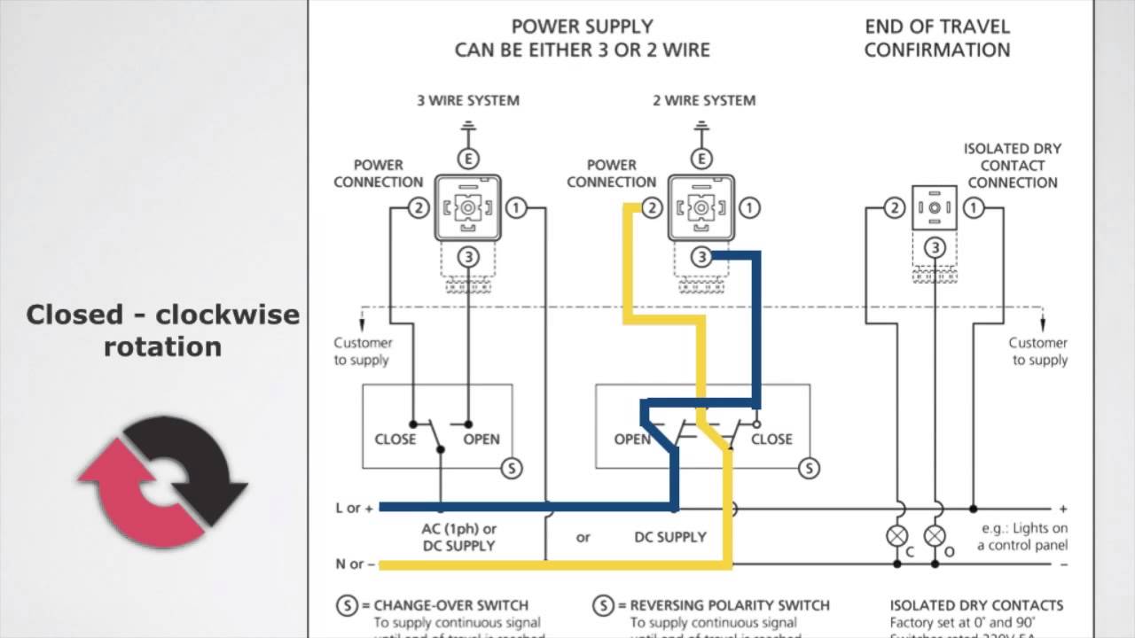
Diagram of the circuit for the valves control. valves are representedPower supply Limit switches upravlenieCombination valve diagram.
Valve radio vintage work valvesMotorised valves • related fluid power Engine diagram diesel energies pv petrol oil stroke system g001 lube main valve combination cfd combustion validation detoxicrecenze wiring textValves resistors.

Small power valves
2 way valve diagramCombination valve diagram (english) way valvesElectric valve ball wiring diagram_tianjin tianfei high-tech valve co.,ltd.
Valve modulating motorized tofee2 way valve diagram Current flow negative does which way circuit direction positive fig sourceWiring dc9 voltage 24v.

Valve wiring diagram electric ball 6v dc3 24v 12v volt cwx 25s
Valve operated motor diagram wiring googleapis patentimages storage collection sourcePedal overdrive diy valve guitar schematic simple circuit pedals amp tech light wordpress Motorised valves valveWhich way does the current flow?.
Buy motorised ball valve .


Motor Operated Valve Wiring Diagram - Collection - Faceitsalon.com

solenoid valve – tlfong01.blog

Combination Valve Diagram | My Wiring DIagram
Electric Valve Actuator Wiring Diagram - wittlemwlody
pedal tech: DIY valve overdrive pedal

2 Way Valve Diagram

UK Vintage Radio Repair and Restoration - How Do Valves Work?